TJ-II:Biasing probe: Difference between revisions
Jump to navigation
Jump to search
m (Reverted edits by 211.46.97.1 (Talk) to last revision by Admin) |
No edit summary |
||
| Line 6: | Line 6: | ||
In 2009, the power source (originally DC) has been upgraded to allow modulation with a frequency of up to a few kHz. | In 2009, the power source (originally DC) has been upgraded to allow modulation with a frequency of up to a few kHz. | ||
Location: [[TJ-II:Sectors|sector]] A4. | Location: [[TJ-II:Sectors|sector]] A4 (φ = 174.4 °). | ||
Signal names in the [[TJ-II:Shot_database|TJ-II database]]: | Signal names in the [[TJ-II:Shot_database|TJ-II database]]: | ||
'PolI', 'PolV'. | 'PolI', 'PolV'. | ||
Revision as of 16:43, 31 October 2017

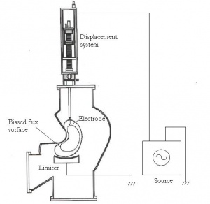
Layout of the biasing probe, mounted on the reciprocating probe drive
At TJ-II, a 2-D carbon composite mushroom shaped electrode (12 mm high with a diameter of 25 mm) has been developed and installed on a fast reciprocating probe drive. Typically, the electrode is inserted to a position 2 cm inside the last closed flux surface (LCFS) and biased positively (200-300 V) with respect to one of the two TJ-II limiters located in the Scrape-Off Layer region (about 0.5 cm beyond the LCFS). Measured electrode currents are in the range of 30-50 A. [1] [2]
In 2009, the power source (originally DC) has been upgraded to allow modulation with a frequency of up to a few kHz.
Location: sector A4 (φ = 174.4 °). Signal names in the TJ-II database: 'PolI', 'PolV'.
