TJ-II:Fast camera: Difference between revisions
No edit summary |
|||
| Line 4: | Line 4: | ||
<ref name="delaCal">[http://onlinelibrary.wiley.com/doi/10.1002/ctpp.201000039/pdf E. de la Cal et al, ''The visible intensified cameras for plasma imaging in the TJ-II stellarator'', Contrib. Plasma Phys. (2010)]</ref>. | <ref name="delaCal">[http://onlinelibrary.wiley.com/doi/10.1002/ctpp.201000039/pdf E. de la Cal et al, ''The visible intensified cameras for plasma imaging in the TJ-II stellarator'', Contrib. Plasma Phys. (2010)]</ref>. | ||
The main system is located in [[TJ-II:Sectors|sector]] B8, [[TJ-II:Ports|port]] B8TANG, viewing the [[TJ-II:Limiter|poloidal limiter]] in sector C3 tangentially. | The main system is located in [[TJ-II:Sectors|sector]] B8, [[TJ-II:Ports|port]] B8TANG, viewing the [[TJ-II:Limiter|poloidal limiter]] in sector C3 tangentially. | ||
== Cameras == | == Cameras == | ||
The newest fast camera employed at TJ-II is a [http://www.photron.com/ Photron] SA1 camera. | The newest fast camera employed at TJ-II is a [http://www.photron.com/ Photron] SA1 camera. | ||
| Line 14: | Line 16: | ||
The dynamic range of the sensor is 8 bits, and the memory size is 8 GB. | The dynamic range of the sensor is 8 bits, and the memory size is 8 GB. | ||
== Image Intensifier for Fast Camera== | == Image Intensifier for Fast Camera== | ||
A [http://sales.hamamatsu.com/en/home.php Hamamatsu] C9548-03BL series image intensifier is used. | A [http://sales.hamamatsu.com/en/home.php Hamamatsu] C9548-03BL series image intensifier is used. | ||
This is a two stage intensifier, including a first GEN II stage with a fast phosphor (P-46) and gain adjustable via the voltage at the MCP, and a second GEN I one (booster) with a fixed gain of 50 and somewhat slower phosphor screen (P-24). Both stages are optically coupled by a Fiber Optic Plate (FOP) which transfers the output signal from the first to the second. | This is a two stage intensifier, including a first GEN II stage with a fast phosphor (P-46) and gain adjustable via the voltage at the MCP, and a second GEN I one (booster) with a fixed gain of 50 and somewhat slower phosphor screen (P-24). Both stages are optically coupled by a Fiber Optic Plate (FOP) which transfers the output signal from the first to the second. | ||
[[File:TJ-II_Fast_camera_diagram.jpg|800px|thumb|center|Schematic diagram of the TJ-II fast camera installation]] | [[File:TJ-II_Fast_camera_diagram.jpg|800px|thumb|center|Schematic diagram of the TJ-II fast camera installation]] | ||
== Videos == | == Videos == | ||
Below are some examples of movies recorded with the fast camera system of TJ-II. | Below are some examples of movies recorded with the fast camera system of TJ-II. Click on the images to see the corresponding movie. | ||
Click on the images to see the corresponding movie. | |||
=== Double imaging to visualize the fine structure of Blobs=== | |||
[[File:25623wComm_Photo000001.jpg|300px|link=http://www-fusion.ciemat.es/fileshare/doc_exchange/camaras/video_DOUBLE_IMAGING.mp4 | |||
A visible fast camera coupled with an image intensifier was employed to view turbulent coherent plasma structures (Blobs) at the gas plume being puffed through a poloidal limiter. The image intensifier amplifies the light intensity thereby allowing the imaging system to be operated at ultra-short exposure times down to 100 ns. | |||
To distinguish real physical signal from noise we get two simultaneous images with the same view and compare them. We call this Double Imaging technique and it allowed us to validate the detected blob shape to scales down to a few millimetres, limited by our optical resolution. | |||
=== Double Imaging of two He I lines #25623=== | === Double Imaging of two He I lines #25623=== | ||
Revision as of 10:17, 10 April 2014
TJ-II disposes of various fast camera systems for plasma imaging [1] [2] [3]. The main system is located in sector B8, port B8TANG, viewing the poloidal limiter in sector C3 tangentially.
Cameras
The newest fast camera employed at TJ-II is a Photron SA1 camera. Sampling speed (measured in frames per second, fps) and image size can be selected, but there is a trade-off:
- 5000 fps with 1024 x 1024 pixels(full frame)
- 10000 fps with 512 x 512 pixels
- 200000 fps (maximum ever employed so far) with 182 x 80 pixels
The dynamic range of the sensor is 8 bits, and the memory size is 8 GB.
Image Intensifier for Fast Camera
A Hamamatsu C9548-03BL series image intensifier is used. This is a two stage intensifier, including a first GEN II stage with a fast phosphor (P-46) and gain adjustable via the voltage at the MCP, and a second GEN I one (booster) with a fixed gain of 50 and somewhat slower phosphor screen (P-24). Both stages are optically coupled by a Fiber Optic Plate (FOP) which transfers the output signal from the first to the second.

Videos
Below are some examples of movies recorded with the fast camera system of TJ-II. Click on the images to see the corresponding movie.
Double imaging to visualize the fine structure of Blobs
[[File:25623wComm_Photo000001.jpg|300px|link=http://www-fusion.ciemat.es/fileshare/doc_exchange/camaras/video_DOUBLE_IMAGING.mp4
A visible fast camera coupled with an image intensifier was employed to view turbulent coherent plasma structures (Blobs) at the gas plume being puffed through a poloidal limiter. The image intensifier amplifies the light intensity thereby allowing the imaging system to be operated at ultra-short exposure times down to 100 ns. To distinguish real physical signal from noise we get two simultaneous images with the same view and compare them. We call this Double Imaging technique and it allowed us to validate the detected blob shape to scales down to a few millimetres, limited by our optical resolution.
Double Imaging of two He I lines #25623
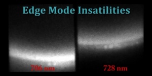
With He I filters (706 nm and 728 nm) and 75 mm lens. Speed: 16000 fps. Exposure time: 60μs. V: 750 V. ECH and NBI plasma with <ne>. Recycling at limiter inserted 25 mm inside the LCFS. Edge Mode Instabilities after density increase with strong crashes and collapse. From the ratio of the filtered lines the <ne> and <Te> can be obtained [4].
Limiter Recycling

Without filter and 75 mm lens. Speed: 54000 fps. Exposure time: 9μs. V: 650 V. ECH plasma with <ne> = 5x10¹⁸ m-3. Recycling at limiter positioned on the LCFS. The bright spot is Blackbody radiation from a glowing Langmuir probe on the limiter corner.
Helium Puffing

Without filter and 75 mm lens. Speed: 100000 fps. Exposure time: 1μs. V: 700 V. ECH plasma with <ne> = 5x10¹⁸ m-3. Helium puffing through the limiter 35 mm outside LCFS.
Lithium emission (Li I filter)

TJ-II plasma observed from a tangential port at 17.5 kHz sampling rate, with a lithium filter and image intensifier. In the field of view, the two most prominent areas of plasma-wall interaction can be seen: the poloidal limiter (lower) and the hardcore (helical limiter). As the plasma transits form ECH to NBI plasmas, the interaction level diminishes and becomes predominantly centered in the limiter. [2] From the lithium emission fluctuations information on the electron density fluctuations can be gained. [3]
Dust

First insertion of the poloidal limiter after a lithiation of the vacuum vessel. Tangential observation, 15 kHz sampling rate. The ejection of lithium flakes from the carbon surface can be seen clearly at the beginning of the discharge. At the end of the video, as the plasma becomes colder, the flakes penetrate deeper into it until they float freely in the post-discharge plasmoid.
References
- ↑ J.A. Alonso et al, Impact of different confinement regimes on the two-dimensional structure of edge turbulence, Plasma Phys. Control. Fusion 48 (2006) B465-B473
- ↑ 2.0 2.1 D. Carralero et al, Turbulence studies by fast camera imaging experiments in the TJII stellarator, Journal of Nuclear Materials 390-391 (2009) 457-460
- ↑ 3.0 3.1 E. de la Cal et al, The visible intensified cameras for plasma imaging in the TJ-II stellarator, Contrib. Plasma Phys. (2010)