TJ-II:Electron Cyclotron Resonant Heating: Difference between revisions
Jump to navigation
Jump to search
No edit summary |
Added figures showing injection lines |
||
| Line 1: | Line 1: | ||
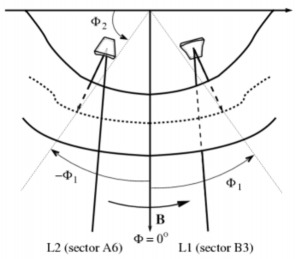
[[File:Beamlines_1.png|300px|thumb|right|Top view of the TJ-II plasma and the injection locations of the two beam lines]] | |||
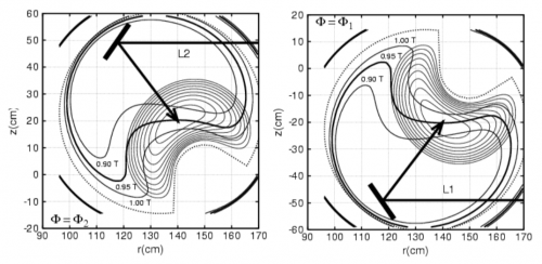
[[File:Beamlines_2.png|500px|thumb|right|Cross sections for the two beam lines, showing the steerable mirrors]] | |||
In the [[TJ-II]] stellarator, the plasmas are created and heated by two 53.2 GHz gyrotrons, each of them delivering up to 300 kW in the 2<sup>nd</sup> harmonic, with X-mode polarisation. | In the [[TJ-II]] stellarator, the plasmas are created and heated by two 53.2 GHz gyrotrons, each of them delivering up to 300 kW in the 2<sup>nd</sup> harmonic, with X-mode polarisation. | ||
<ref>[[doi:10.1088/0741-3335/30/7/008|F. Castejón and J. Guasp, ''Microwave injection in heliac device TJ-II'', Plasma Phys. Control. Fusion '''30''' (1988) 907-911]]</ref> | <ref>[[doi:10.1088/0741-3335/30/7/008|F. Castejón and J. Guasp, ''Microwave injection in heliac device TJ-II'', Plasma Phys. Control. Fusion '''30''' (1988) 907-911]]</ref> | ||
Revision as of 17:13, 12 October 2018


In the TJ-II stellarator, the plasmas are created and heated by two 53.2 GHz gyrotrons, each of them delivering up to 300 kW in the 2nd harmonic, with X-mode polarisation. [1] The power is transmitted to the plasma by two quasi-optical transmission lines (QTL1 and QTL2). [2] The power is delivered to the sector B3 (for QTL1) and A6 (for QTL2). The last mirror of each line is a steerable mirror located inside the vacuum vessel, which allows for perpendicular and oblique injection. [3] [4] [5] [6] The gyrotrons can be modulated for perturbative transport experiments [7] and can be used to drive current. [8]
See also
Panorama showing the TJ-II ECRH system
References
- ↑ F. Castejón and J. Guasp, Microwave injection in heliac device TJ-II, Plasma Phys. Control. Fusion 30 (1988) 907-911
- ↑ A. Fernández et al, Quasioptical Transmission Lines for ECRH at TJ-II Stellarator, International Journal of Infrared and Millimeter Waves 21, 12 (2000) 1945-1957
- ↑ A. Fernández et al, Design of the upgraded TJ-II quasi-optical transmission line, Conference Digest, 25th International Conference on Infrared and Millimeter Waves (2000) 91 - 92
- ↑ A. Fernandez et al, EC waves polarization control in the TJ-II stellarator, Joint 32nd International Conference on Infrared and Millimeter Waves (2007)
- ↑ A. Fernández et al, Gyrotron Radiation Affected by a Controlled Modulated Reflector: High Power Experiment, International Journal of Infrared and Millimeter Waves 28, 9 (2007) 705-711
- ↑ A. Fernández et al, Performance of the TJ-II ECRH system with the new −80 kV 50 A high voltage power supply, Fusion Engineering and Design 84, Issues 2-6 (2009) 772-775
- ↑ S. Eguilior et al, Heat wave experiments on TJ-II flexible heliac, Plasma Phys. Control. Fusion 45 (2003) 105–120
- ↑ V. Tribaldos et al, Electron cyclotron heating and current drive in the TJ-II stellarator, Plasma Phys. Control. Fusion 40 (1998) 2113