TJ-II:Reflectometry: Difference between revisions
Updated and corrected references |
|||
| (12 intermediate revisions by 3 users not shown) | |||
| Line 1: | Line 1: | ||
== Profile Reflectometer == | == Profile Reflectometer == | ||
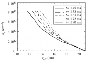
[[File:Reflectometry density profile.png|300px|thumb|right|Time evolution of density profiles measured by the AM reflectometer during the transition to an enhanced confinement mode (from: Estrada et al., Plasma Phys. Control. Fusion '''43''' (2001) | [[File:Reflectometry density profile.png|300px|thumb|right|Time evolution of density profiles measured by the AM reflectometer during the transition to an enhanced confinement mode (from: <ref name="Estrada">T. Estrada et al., [[doi:10.1088/0741-3335/43/11/308|Plasma Phys. Control. Fusion '''43''' (2001) 1535–1545]]</ref>)]] | ||
[[TJ-II]] has an AM reflectometer | [[TJ-II]] has an AM reflectometer<ref name="Estrada"></ref> | ||
<ref> | |||
for measuring electron density profiles with a temporal resolution of 2 ms. | for measuring electron density profiles with a temporal resolution of 2 ms. | ||
Separate antennas are used for launching and receiving the signal. The antennas are located in the equatorial plane of the toroidal cross-section at φ = | Separate antennas are used for launching and receiving the signal. The antennas are located in the equatorial plane of the toroidal cross-section at φ = 135° (between [[TJ-II:Sectors|sectors]] A4 and A5), and view the plasma from the low-field side. | ||
Inside the [[TJ-II:Vacuum system|vacuum vessel]], a fundamental wave-guide is used to transmit the signal from the closest port (A4top: φ = | Inside the [[TJ-II:Vacuum system|vacuum vessel]], a fundamental wave-guide is used to transmit the signal from the closest port ([[TJ-II:Ports|A4top]]: φ = 128.17°, θ = 90°) to the desired launching location (φ = 135°, θ = 180°). | ||
Signal names in the [[TJ-II:Shot_database|TJ-II database]]: | |||
quadrature signals: 'SinAM', 'CosAM'; frequency ramp: 'Rampa'. | |||
== Fluctuation Reflectometer == | == Fluctuation Reflectometer == | ||
A fast frequency hopping reflectometer | A fast frequency hopping reflectometer | ||
<ref> | <ref>L. Cupido, J. Sánchez and T. Estrada, [[doi:10.1063/1.1788834|Rev. Sci. Intrum. '''75''' (2004) 3865]]</ref> | ||
working in the Q-band (33 - 50 GHz) was used from 2004 - 2008 in [[TJ-II:Sectors|sector]] B8 in perpendicular incidence (''conventional'' reflectometry). The system allowed studies of the velocity shear layer in [[TJ-II]] | working in the Q-band (33 - 50 GHz) was used from 2004 - 2008 in [[TJ-II:Sectors|sector]] B8 in perpendicular incidence (''conventional'' reflectometry). The system allowed studies of the velocity shear layer in [[TJ-II]] | ||
<ref> | <ref>T. Estrada, E. Blanco, L. Cupido, M.E. Manso, and J. Sánchez, [[doi:10.1088/0029-5515/46/9/S14|Nucl. Fusion '''46''' (2006) S792–S798]]</ref> | ||
and of the radial position of its origin. | and of the radial position of its origin. | ||
<ref> | <ref>T. Happel, T. Estrada and C. Hidalgo, ''First experimental observation of a two-step process in the development of the edge velocity shear layer in a fusion plasma'', [[doi:10.1209/0295-5075/84/65001|EPL 84 (2008) 65001]]</ref> | ||
== Doppler Reflectometer == | == Doppler Reflectometer == | ||
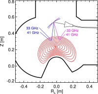
[[File:DRscheme.jpg|200px|thumb|right|Schematic drawing of the Doppler Reflectometer System of [[TJ-II]]. The rays are calculated using the 3D ray/beam-tracing code [[ | [[File:DRscheme.jpg|200px|thumb|right|Schematic drawing of the Doppler Reflectometer System of [[TJ-II]]. The rays are calculated using the 3D ray/beam-tracing code [[TRUBA]].]] | ||
Since February 2009, the frequency hopping system is in operation in oblique incidence (''Doppler'' reflectometry, [[TJ-II:Sectors|sector]] C6) | Since February 2009, the frequency hopping system is in operation in oblique incidence (''Doppler'' reflectometry, [[TJ-II:Sectors|sector]] C6, φ = 337°) | ||
<ref> | <ref>T. Happel, T. Estrada, E. Blanco, V. Tribaldos, A. Cappa, and A. Bustos, [[doi:10.1063/1.3160106|Rev. Sci. Instrum. '''80''' (2009) 073502]]</ref> | ||
, measuring plasma density fluctuation velocities and their wave number spectra. The system is able to measure in a radial range of about ρ = 0.6 - 0.9 (ρ = r/a is the [[effective plasma radius]]) and the perpendicular wavenumber can be selected between 3 and 15 cm<sup>-1</sup>. | , measuring plasma density fluctuation velocities and their wave number spectra. The system is able to measure in a radial range of about ρ = 0.6 - 0.9 (ρ = r/a is the [[effective plasma radius]]) and the perpendicular wavenumber can be selected between ''k''<sub>⊥</sub> = 3 and 15 cm<sup>-1</sup>. | ||
The system consists of a circular choked-corrugated antenna | The system consists of a circular choked-corrugated antenna | ||
<ref> | <ref>J. Teniente, R. Gonzalo, and C. del-Rio, [[doi:10.1109/LAWP.2006.881919 |IEEE Antennas Wireless Propag. Lett. '''5''' (2006) 380]]</ref> | ||
(fabricated by the ''Antenna Group of the Public University of Navarra, Spain'') which emits a microwave beam with a gaussian electric field distribution. The beam is reflected by a steerable ellipsoidal mirror to the plasma. The mirror serves for two purposes: 1) focus the microwave beam to the region where backscattering takes place and 2) change the angle of incidence between beam and plasma, giving the possibility to select the turbulence scale to be measured. The [[Effective_plasma_radius|radial]] position of scattering and the probed perpendicular wavenumber are calculated after the discharge using the 3D ray/beam-tracing code [[TRUBA]]. | (fabricated by the [http://antenas.unavarra.es/ ''Antenna Group of the Public University of Navarra, Spain'']) which emits a microwave beam with a gaussian electric field distribution. The beam is reflected by a steerable ellipsoidal mirror to the plasma. The mirror serves for two purposes: 1) focus the microwave beam (obtaining plane wavefronts) to the region where backscattering takes place and 2) change the angle of incidence between beam and plasma, giving the possibility to select the turbulence scale to be measured. | ||
Different scenarios can be realized: Positive or negative incidence angles of the incident beam or perpendicular incidence, which is equivalent to a conventional reflectometer system. The [[Effective_plasma_radius|radial]] position of scattering and the probed perpendicular wavenumber are calculated after the discharge using the 3D ray/beam-tracing code [[TRUBA]]. | |||
==References== | ==References== | ||
<references /> | <references /> | ||
Latest revision as of 07:56, 18 May 2015
Profile Reflectometer

TJ-II has an AM reflectometer[1] for measuring electron density profiles with a temporal resolution of 2 ms. Separate antennas are used for launching and receiving the signal. The antennas are located in the equatorial plane of the toroidal cross-section at φ = 135° (between sectors A4 and A5), and view the plasma from the low-field side. Inside the vacuum vessel, a fundamental wave-guide is used to transmit the signal from the closest port (A4top: φ = 128.17°, θ = 90°) to the desired launching location (φ = 135°, θ = 180°).
Signal names in the TJ-II database: quadrature signals: 'SinAM', 'CosAM'; frequency ramp: 'Rampa'.
Fluctuation Reflectometer
A fast frequency hopping reflectometer [2] working in the Q-band (33 - 50 GHz) was used from 2004 - 2008 in sector B8 in perpendicular incidence (conventional reflectometry). The system allowed studies of the velocity shear layer in TJ-II [3] and of the radial position of its origin. [4]
Doppler Reflectometer

Since February 2009, the frequency hopping system is in operation in oblique incidence (Doppler reflectometry, sector C6, φ = 337°) [5] , measuring plasma density fluctuation velocities and their wave number spectra. The system is able to measure in a radial range of about ρ = 0.6 - 0.9 (ρ = r/a is the effective plasma radius) and the perpendicular wavenumber can be selected between k⊥ = 3 and 15 cm-1.
The system consists of a circular choked-corrugated antenna [6] (fabricated by the Antenna Group of the Public University of Navarra, Spain) which emits a microwave beam with a gaussian electric field distribution. The beam is reflected by a steerable ellipsoidal mirror to the plasma. The mirror serves for two purposes: 1) focus the microwave beam (obtaining plane wavefronts) to the region where backscattering takes place and 2) change the angle of incidence between beam and plasma, giving the possibility to select the turbulence scale to be measured.
Different scenarios can be realized: Positive or negative incidence angles of the incident beam or perpendicular incidence, which is equivalent to a conventional reflectometer system. The radial position of scattering and the probed perpendicular wavenumber are calculated after the discharge using the 3D ray/beam-tracing code TRUBA.
References
- ↑ 1.0 1.1 T. Estrada et al., Plasma Phys. Control. Fusion 43 (2001) 1535–1545
- ↑ L. Cupido, J. Sánchez and T. Estrada, Rev. Sci. Intrum. 75 (2004) 3865
- ↑ T. Estrada, E. Blanco, L. Cupido, M.E. Manso, and J. Sánchez, Nucl. Fusion 46 (2006) S792–S798
- ↑ T. Happel, T. Estrada and C. Hidalgo, First experimental observation of a two-step process in the development of the edge velocity shear layer in a fusion plasma, EPL 84 (2008) 65001
- ↑ T. Happel, T. Estrada, E. Blanco, V. Tribaldos, A. Cappa, and A. Bustos, Rev. Sci. Instrum. 80 (2009) 073502
- ↑ J. Teniente, R. Gonzalo, and C. del-Rio, IEEE Antennas Wireless Propag. Lett. 5 (2006) 380