TJ-II:Bolometry: Difference between revisions
Jump to navigation
Jump to search
No edit summary |
No edit summary |
||
| (14 intermediate revisions by 2 users not shown) | |||
| Line 1: | Line 1: | ||
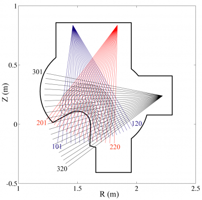
[[File:TJ-II_Bolometer.png| | [[File:TJ-II_Bolometer.png|400px|thumb|right|The TJ-II bolometry system for tomographic reconstruction ([[TJ-II:Sectors|sector]] B7, φ = 255.5 °)]] | ||
TJ-II has several bolometry systems: | TJ-II has several bolometry systems | ||
* Three 20-channel pinhole cameras in [[TJ-II:Sectors|sector]] B7, monitoring the same poloidal section and used for tomographic reconstructions <ref>[[EBITA]]</ref> of the total plasma emissivity | <ref>M.A. Ochando et al., ''Up-Down and In-Out Asymmetry Monitoring Based on Broadband Radiation Detectors'', [http://www.new.ans.org/pubs/journals/fst/a_1252 Fusion Sci. Technol. '''50''', 313 (2006)]</ref> | ||
* | <ref>B. Zurro et al, ''Method to deduce local impurity transport quantities from the evolution of tomographically reconstructed bolometer signals during tracer injection at TJ-II'', [[doi:10.1063/1.1787585|Rev. Sci. Instrum. '''75''' (2004) 4231]]</ref> | ||
* | : | ||
* Three 20-channel pinhole cameras in [[TJ-II:Sectors|sector]] B7, monitoring the same poloidal section and used for tomographic reconstructions <ref>[[EBITA]]</ref><ref>[[TJ-II:Tomography]]</ref> of the total plasma emissivity. <ref>E. Barrera et al, ''Real-time data acquisition and parallel data processing solution for TJ-II Bolometer arrays diagnostic'', [[doi:10.1016/j.fusengdes.2006.04.046|Fusion Engineering and Design '''81''', Issues 15-17 (2006) 1863-1867]]</ref> Signal names in the [[TJ-II:Shot_database|TJ-II database]]: 'BO101' ... 'BO120', 'BO201' ... 'BO220', 'BO301' ... 'BO320'. | |||
* Three 16-channel cameras in [[TJ-II:Sectors|sectors]] A7, C2, D7. Signal names in the [[TJ-II:Shot_database|TJ-II database]]: 'ABOL1' ... 'ABOL16', 'CBOL1' ... 'CBOL16', 'DBOL1' ... 'DBOL16'. | |||
* Six global bolometry monitors. Signal names in the [[TJ-II:Shot_database|TJ-II database]]: 'BOL1', 'BOL3', 'BOL6'; 'BOL2', 'BOL5', 'BOL7'. | |||
==References== | ==References== | ||
<references /> | <references /> | ||
Latest revision as of 15:36, 29 October 2015

TJ-II has several bolometry systems [1] [2]
- Three 20-channel pinhole cameras in sector B7, monitoring the same poloidal section and used for tomographic reconstructions [3][4] of the total plasma emissivity. [5] Signal names in the TJ-II database: 'BO101' ... 'BO120', 'BO201' ... 'BO220', 'BO301' ... 'BO320'.
- Three 16-channel cameras in sectors A7, C2, D7. Signal names in the TJ-II database: 'ABOL1' ... 'ABOL16', 'CBOL1' ... 'CBOL16', 'DBOL1' ... 'DBOL16'.
- Six global bolometry monitors. Signal names in the TJ-II database: 'BOL1', 'BOL3', 'BOL6'; 'BOL2', 'BOL5', 'BOL7'.
References
- ↑ M.A. Ochando et al., Up-Down and In-Out Asymmetry Monitoring Based on Broadband Radiation Detectors, Fusion Sci. Technol. 50, 313 (2006)
- ↑ B. Zurro et al, Method to deduce local impurity transport quantities from the evolution of tomographically reconstructed bolometer signals during tracer injection at TJ-II, Rev. Sci. Instrum. 75 (2004) 4231
- ↑ EBITA
- ↑ TJ-II:Tomography
- ↑ E. Barrera et al, Real-time data acquisition and parallel data processing solution for TJ-II Bolometer arrays diagnostic, Fusion Engineering and Design 81, Issues 15-17 (2006) 1863-1867