TJ-II:Heavy Ion Beam Probe
TJ-II disposes of Heavy Ion Beam Probe systems.
HIBP 1

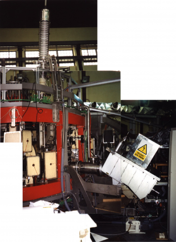
The advanced Heavy Ion Beam Probe can simultaneously measure the plasma electric potential φ, the electron density ne, and a poloidal magnetic field component Bp at a point inside the plasma. [1] [2] [3] [4] [5] [6] [7] This point can be scanned through the plasma cross-section by varying the deflection potentials (active beam control). A multiple cell array detector (MCAD) has been developed to investigate the spatial structure of plasma turbulence. [8] The system is located in sector B4.

HIBP 2
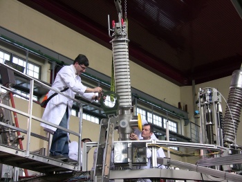
A second, similar system is currently being installed in sector A4 (see photo).

Operation principle
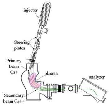
The Heavy Ion Beam Probe (HIBP) is a unique diagnostic for its ability to measure plasma electric potential well inside the plasma column, where no material probes can be inserted. The operating principle is as follows: heavy ions with charge (Cs in the case of TJ-II) are accelerated to high energies (several hundred keV) and injected as a continuous jet into the plasma column. The interaction with the plasma yields a fan of secondary ions that are more strongly deflected by the magnetic field. Those secondary ions produced in the so-called `sample volume' are collected in an energy analyser. Their energy contains information on the electric potential in the sample volume. Trajectory reconstruction codes allow us to measure the position and reltive potential of the sample volume.
Formal expression of the electric potential
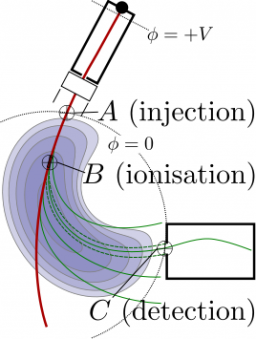
Refering to the figure, we will denote as , and the injection, ionization and detection points respectively. The Hamiltonian of a charge in an electromagnetic field is

From the Hamiltonian equations we obtain the ion trajectory . The ion's energy variation from to is given as
and using the above expression for the Hamiltonian we obtain
and thus
We use the notation
In the range of ion energies and plasma temperatures commonly found in magnetic fusion experiments the main ionizing collision is electron impact . Because of the large mass ratio between the heavy ions and light electrons () we can regard the collision as an ionizing process with no change in the ion momentum and kinetic energy.
The extra positive charge after the ionization gives the ion an energy increment
and therefore the total energy change between and is
Similarly, the energy change between and is
Summing the above energy variations gives
In most situations, the energy difference (or the electric potential energy inside the plasma) is much larger than the energy increment caused by the fluctuating electromagnetic fields which tends to cancel out along the ion's trajectory. The electric potentials of the injection and detection points are both close to the vacuum vessel potentials so that . Therefore this simplifies to
Operational expression for the electric potential
The energy analyser of the HIBP diagnostic at TJ-II is of the Proca-Green type. The kinetic energy of the secondary ions entering the analyser is given by
where is the deflecting electric potential in the analyser gird, are the currents measured on the up and down plates of the analyser and and are adimensional geometric factors depending on construction parameters and on the entrance angle of the ions entering the analyser. The kinetic energy of the ions at the injection point can be written as their charge times the accelerating potential in the injector, i.e.,
Substituting this and the Proca-green expression for the enery into the formula for the electtric potential and inserting, for the particular case of TJ-II, y , one gets
In a stellarator it is possible to calibrate the measurement of the plasma electric potential. After the end of the plasma discharge but still during the flat-top of the machine currents the injection of a short pulse of neutral gas provides a zero-potential signal
Subtracting the above equations a simplified expression for the electric potential is obtained
The ionization rate of primary ions in a plasma volume is approximately proportional to the local electron density. For the high energy neutral beam and the low density plasmas, as found in the TJ-II device, the attenuation of the secondary beam along its trajectory from the ionization or sample volume to the analyser is negligible. In this situation, the total current on the analyser plates is approximately proportional to the electron density in the sample volume
Data Analysis Tools
References
- ↑ I.S. Bondarenko et al., Installation of an advanced heavy ion beam diagnostic on the TJ-II stellarator, Rev. Sci. Instrum. 72, 583 (2001)
- ↑ L.I. Krupnik et al., The first operation of the advanced heavy ion beam probing diagnostic on the TJ-II flexible heliac, Fusion Engineering and Design 56-57 (2001) 935
- ↑ I.S. Bondarenko et al, High intensity alkali ion sources for plasma diagnostics, Rev. Sci. Instrum. 75 (2004) 1826
- ↑ L. Krupnik et al, Radial electric fields and confinement in the TJ-II stellarator, Czechoslovak Journal of Physics 55, 3 (2005) 317-339(23)
- ↑ L. Pereira et al, Control and data acquisition system for the multiple cell array detector of the TJ-II heavy ion beam diagnostic, Fusion Engineering and Design 81, Issues 15-17 (2006) 1885-1889
- ↑ A.V. Melnikov et al, Plasma Potential Evolution Study by HIBP Diagnostic During NBI Experiments in the TJ-II Stellarator, Fusion Science and Technology 51, 1 (2007) 31-37
- ↑ A.V. Melnikov, L.I. Krupnik, C. Hidalgo, et al, Diagnostic advances in Heavy Ion Beam Probing in the T-10 tokamak and TJ-II stellarator, [http://ocs.ciemat.es/EPS2013PAP/pdf/O6.505.pdf 40th EPS Conference (2013) O6.505
- ↑ B. Gonçalves et al, Operation of a multiple cell array detector in plasma experiments with a heavy ion beam diagnostic, Rev. Sci. Instrum. 75 (2004) 3511