TJ-II:Neutral Beam Injection: Difference between revisions
No edit summary |
|||
| (35 intermediate revisions by 2 users not shown) | |||
| Line 1: | Line 1: | ||
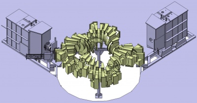
[[TJ-II]] disposes of two neutral beam injectors ( | [[TJ-II]] disposes of two neutral beam injectors (co and counter, corresponding to NBI1 and NBI2, respectively), each of | ||
which can produce ≤ 300 ms pulses of neutral hydrogen | which can produce ≤ 300 ms pulses of neutral hydrogen | ||
accelerated to 40 keV, to provide up to 1.2 MW of absorbed | accelerated to 40 keV, to provide up to 1.2 MW of absorbed | ||
additional heating for central electron densities up to 1.6×10<sup>20</sup> | additional heating for central electron densities up to 1.6×10<sup>20</sup> | ||
m<sup>-3</sup>. | m<sup>-3</sup>. | ||
<ref>[http://www | <ref>J. Guasp, M. Liniers, ''Theoretical evaluations of Neutral beam Injection efficiency for the TJ-II helical-axis stellarator'', [http://www.ans.org/store/j_30199 Fusion technology '''24''', 3, 251 (1993)]</ref> | ||
<ref> | <ref>J. Guasp, M. Liniers, ''Loss cone structure for ions in the TJ-II helical axis stellarator. Part I: properties without a radial electric field'', [[doi:10.1088/0029-5515/40/3/309|Nucl. Fusion '''40''' (2000) 397-409]]</ref> | ||
<ref>[http:// | <ref>J. Guasp, M. Liniers, ''Loss cone structure for ions in the TJ-II helical axis stellarator. Part II: radial electric field effects'', [[doi:10.1088/0029-5515/40/3/310|Nucl. Fusion '''40''' (2000) 411-427]]</ref> | ||
<ref>J. Guasp, M. Liniers, C. Fuentes, and G. Barrera, ''Thermal load calculations at TJ-II vacuum vessel under NBI,'' [http://www.new.ans.org/store/j_75 Fusion Tech., '''35''', pp. 32-41 (1999)]</ref> | |||
<ref>C. Fuentes et al, ''Neutral beam injection optimization at TJ-II'', [[doi:10.1016/j.fusengdes.2005.06.315|Fusion Engineering and Design '''74''', Issues 1-4 (2005) 249-253]]</ref> | |||
The beams also drive current in the plasma. | |||
<ref>S. Mulas et al, [[doi:10.1088/1741-4326/acca92|Nucl. Fusion 63 (2023) 066026]]</ref> | |||
NBI1 is located in [[TJ-II:Sectors|sector]] D8. | NBI1 is located in [[TJ-II:Sectors|sector]] D8. | ||
NBI2 is located in [[TJ-II:Sectors|sector]] C1. | NBI2 is located in [[TJ-II:Sectors|sector]] C1. | ||
[[File:TJ-II_NBI.png| | {| border="0" | ||
|- valign="top" | |||
| [[File:NBI 1y2.jpg|400px|thumb|TJ-II vacuum vessel and the two NBI injectors. Left: NBI1; right: NBI2]] | |||
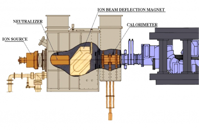
| [[File:TJ-II_NBI.png|400px|thumb|Diagram of an NBI injector, coupled to TJ-II]] | |||
|- | |||
|} | |||
=== Power supply === | |||
The two high voltage power supplies feeding the acceleration grids of the injectors are of the transformer–rectifier type, taking their primary energy from a pulsed [[TJ-II:Power supply|flywheel generator]], and are coupled to the acceleration grids through a switching device. | |||
<ref>J. Alonso et al, ''High voltage power supplies for the neutral beam injectors of the stellarator TJ-II'', [[doi:10.1016/S0920-3796(01)00389-1|Fusion Engineering and Design '''56-57''' (2001) 693-697]]</ref> | |||
=== Control system === | |||
The NBI system has its own control system, based on [[:Wikipedia:VMEbus|VMEbus]], with controller boards running the [[:Wikipedia:OS9|OS9]] real-time operating system. | |||
<ref>L. Martínez-Laso et al, ''TJ-II neutral beam injectors control and data acquisition system'', [[doi:10.1016/S0920-3796(01)00349-0|Fusion Engineering and Design '''56-57''' (2001) 477-480]]</ref> | |||
<ref>R. Carrasco et al, ''The NBI control system for the TJ-II'', [[doi:10.1016/j.fusengdes.2006.04.014|Fusion Engineering and Design '''81''', Issues 15-17 (2006) 1813-1816]]</ref> | |||
=== Vacuum system === | |||
In order to keep reionization losses at an acceptable level, the maximum allowed pressure during the beam pulse is 10<sup>−4</sup> mbar, which requires an installed pumping speed of 350,000 l/s. Titanium getter pumps have been chosen as the primary vacuum system for these injectors. Base pressures in the range of 5 × 10<sup>−9</sup> mbar are attainable with titanium pump operation. | |||
<ref>M. Liniers et al, ''Vacuum system of the neutral beam injectors at the stellarator TJ-II'', [[doi:10.1016/S0042-207X(02)00208-7|Vacuum '''67''', Issues 3-4 (2002) 379-384]]</ref> | |||
=== Calorimeter === | |||
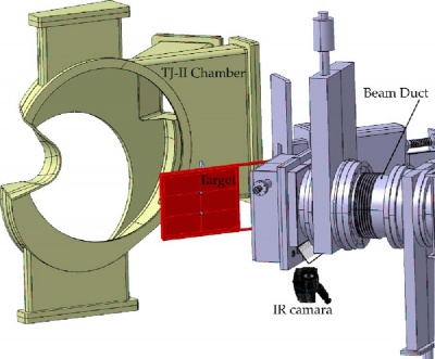
[[File:TJ-II NBI Calorimeter.jpg|400px|thumb|right|The target calorimeter (red) in its operating position. Only part of the vacuum vessel is shown. The neutral beam is injected from the right. The infrared (IR) camera (below) views the calorimeter via a mirror]] | |||
A carbon fiber composite (CFC) target calorimeter has been installed to study the power density distribution of the neutral beams in situ. The thermographic print of the beam can be recorded using an infrared camera, permitting a reliable analysis due to the highly anisotropic thermal conductivity of the target material. Direct conversion from temperature to power density is possible due to independent thermocouple measurements on two adiabatically mounted copper buttons. With the combined thermographic and calorimetric measurements it has been possible to determine the power density distribution of the beams. | |||
<ref>C. Fuentes et al, ''Thermographic calorimetry of the neutral beam injectors heating beams at TJ-II'', [[doi:10.1063/1.2220067|Rev. Sci. Instrum. '''77''' (2006) 10E519]]</ref> | |||
<ref>C. Fuentes et al, ''Power transmission of the neutral beam heating beams at TJ-II'', [[doi:10.1016/j.fusengdes.2007.07.054|Fusion Engineering and Design '''82''', Issues 5-14 (2007) 926-932]]</ref> | |||
<ref>[[Media:Master_thesis_julius_damba.pdf|J. Damba, ''Beam Transmission Monitoring of the TJ-II Neutral Beam Injectors'', European Master of Science in Nuclear Fusion Physics and Engineering (Erasmus Mundus Programme, 2014)]]</ref> | |||
=== Power and particle balance === | |||
In the analysis of the confinement and transport properties of NBI heated plasmas, a proper evaluation of the power and particle balance is necessary. In order to achieve that, a number of experimental studies have been carried out to determine the beam power transmission and beam contribution to plasma fuelling. | |||
<ref>M. Liniers, G. Wolfers, et al., ''Beamline duct monitoring of the TJ-II Neutral Beam Injectors'', [[doi:10.1016/j.fusengdes.2013.04.014|Fusion Engineering and Design '''88''', Issues 6-8 (2013) 960-963]]</ref> | |||
<ref>M. Liniers, J. Damba, et al., ''Beam transmission dependence on beam parameters for TJ-II Neutral Beam Injectors '', [[doi:10.1016/j.fusengdes.2017.05.104|Fusion Engineering and Design (2017) ]]</ref> | |||
=== Signal names in the [[TJ-II:Shot database|TJ-II database]] === | |||
UACCEL1, IACCEL1 (NBI1) and UACCEL2, IACCEL2 (NBI2). U = voltage, I = current. | |||
== See also == | |||
[[OLMAT]] | |||
==References== | ==References== | ||
<references /> | <references /> | ||
Latest revision as of 08:43, 17 July 2024
TJ-II disposes of two neutral beam injectors (co and counter, corresponding to NBI1 and NBI2, respectively), each of which can produce ≤ 300 ms pulses of neutral hydrogen accelerated to 40 keV, to provide up to 1.2 MW of absorbed additional heating for central electron densities up to 1.6×10²⁰ m-3. [1] [2] [3] [4] [5] The beams also drive current in the plasma. [6]
NBI1 is located in sector D8. NBI2 is located in sector C1.
 |
 |
Power supply
The two high voltage power supplies feeding the acceleration grids of the injectors are of the transformer–rectifier type, taking their primary energy from a pulsed flywheel generator, and are coupled to the acceleration grids through a switching device. [7]
Control system
The NBI system has its own control system, based on VMEbus, with controller boards running the OS9 real-time operating system. [8] [9]
Vacuum system
In order to keep reionization losses at an acceptable level, the maximum allowed pressure during the beam pulse is 10−4 mbar, which requires an installed pumping speed of 350,000 l/s. Titanium getter pumps have been chosen as the primary vacuum system for these injectors. Base pressures in the range of 5 × 10⁻⁹ mbar are attainable with titanium pump operation. [10]
Calorimeter

A carbon fiber composite (CFC) target calorimeter has been installed to study the power density distribution of the neutral beams in situ. The thermographic print of the beam can be recorded using an infrared camera, permitting a reliable analysis due to the highly anisotropic thermal conductivity of the target material. Direct conversion from temperature to power density is possible due to independent thermocouple measurements on two adiabatically mounted copper buttons. With the combined thermographic and calorimetric measurements it has been possible to determine the power density distribution of the beams. [11] [12] [13]
Power and particle balance
In the analysis of the confinement and transport properties of NBI heated plasmas, a proper evaluation of the power and particle balance is necessary. In order to achieve that, a number of experimental studies have been carried out to determine the beam power transmission and beam contribution to plasma fuelling. [14] [15]
Signal names in the TJ-II database
UACCEL1, IACCEL1 (NBI1) and UACCEL2, IACCEL2 (NBI2). U = voltage, I = current.
See also
References
- ↑ J. Guasp, M. Liniers, Theoretical evaluations of Neutral beam Injection efficiency for the TJ-II helical-axis stellarator, Fusion technology 24, 3, 251 (1993)
- ↑ J. Guasp, M. Liniers, Loss cone structure for ions in the TJ-II helical axis stellarator. Part I: properties without a radial electric field, Nucl. Fusion 40 (2000) 397-409
- ↑ J. Guasp, M. Liniers, Loss cone structure for ions in the TJ-II helical axis stellarator. Part II: radial electric field effects, Nucl. Fusion 40 (2000) 411-427
- ↑ J. Guasp, M. Liniers, C. Fuentes, and G. Barrera, Thermal load calculations at TJ-II vacuum vessel under NBI, Fusion Tech., 35, pp. 32-41 (1999)
- ↑ C. Fuentes et al, Neutral beam injection optimization at TJ-II, Fusion Engineering and Design 74, Issues 1-4 (2005) 249-253
- ↑ S. Mulas et al, Nucl. Fusion 63 (2023) 066026
- ↑ J. Alonso et al, High voltage power supplies for the neutral beam injectors of the stellarator TJ-II, Fusion Engineering and Design 56-57 (2001) 693-697
- ↑ L. Martínez-Laso et al, TJ-II neutral beam injectors control and data acquisition system, Fusion Engineering and Design 56-57 (2001) 477-480
- ↑ R. Carrasco et al, The NBI control system for the TJ-II, Fusion Engineering and Design 81, Issues 15-17 (2006) 1813-1816
- ↑ M. Liniers et al, Vacuum system of the neutral beam injectors at the stellarator TJ-II, Vacuum 67, Issues 3-4 (2002) 379-384
- ↑ C. Fuentes et al, Thermographic calorimetry of the neutral beam injectors heating beams at TJ-II, Rev. Sci. Instrum. 77 (2006) 10E519
- ↑ C. Fuentes et al, Power transmission of the neutral beam heating beams at TJ-II, Fusion Engineering and Design 82, Issues 5-14 (2007) 926-932
- ↑ J. Damba, Beam Transmission Monitoring of the TJ-II Neutral Beam Injectors, European Master of Science in Nuclear Fusion Physics and Engineering (Erasmus Mundus Programme, 2014)
- ↑ M. Liniers, G. Wolfers, et al., Beamline duct monitoring of the TJ-II Neutral Beam Injectors, Fusion Engineering and Design 88, Issues 6-8 (2013) 960-963
- ↑ M. Liniers, J. Damba, et al., Beam transmission dependence on beam parameters for TJ-II Neutral Beam Injectors , Fusion Engineering and Design (2017)