TJ-II:Neutral Beam Injection: Difference between revisions
No edit summary |
No edit summary |
||
| Line 5: | Line 5: | ||
m<sup>-3</sup>. | m<sup>-3</sup>. | ||
<ref>[http://www.new.ans.org/store/j_75 J. Guasp, M. Liniers, C. Fuentes, and G. Barrera, ''Thermal load calculations at TJ-II vacuum vessel under NBI,'' Fusion Tech., '''35''', pp. 32-41 (1999)]</ref> | <ref>[http://www.new.ans.org/store/j_75 J. Guasp, M. Liniers, C. Fuentes, and G. Barrera, ''Thermal load calculations at TJ-II vacuum vessel under NBI,'' Fusion Tech., '''35''', pp. 32-41 (1999)]</ref> | ||
<ref>[ | <ref>[[doi:10.1016/j.fusengdes.2005.06.315|C. Fuentes et al, ''Neutral beam injection optimization at TJ-II'', Fusion Engineering and Design '''74''', Issues 1-4 (2005) 249-253]]</ref> | ||
<ref>[[doi:10.1016/j.fusengdes.2013.04.014|M. Liniers, G. Wolfers,J.A. Sebastián, et al, ''Beamline duct monitoring of the TJ-II neutral beam injectors'', Fusion Engineering and Design '''88''', Issues 6-8 (2013), 960–963]]</ref> | |||
NBI1 is located in [[TJ-II:Sectors|sector]] D8. | NBI1 is located in [[TJ-II:Sectors|sector]] D8. | ||
| Line 20: | Line 21: | ||
The two high voltage power supplies feeding the acceleration grids of the injectors are of the transformer–rectifier type, taking their primary energy from a pulsed [[TJ-II:Power supply|flywheel generator]], and are coupled to the acceleration grids through a switching device. | The two high voltage power supplies feeding the acceleration grids of the injectors are of the transformer–rectifier type, taking their primary energy from a pulsed [[TJ-II:Power supply|flywheel generator]], and are coupled to the acceleration grids through a switching device. | ||
<ref>[ | <ref>[[doi:10.1016/S0920-3796(01)00389-1|J. Alonso et al, ''High voltage power supplies for the neutral beam injectors of the stellarator TJ-II'', Fusion Engineering and Design '''56-57''' (2001) 693-697]]</ref> | ||
=== Control system === | === Control system === | ||
The NBI system has its own control system, based on [[:Wikipedia:VMEbus|VMEbus]], with controller boards running the [[:Wikipedia:OS9|OS9]] real-time operating system. | The NBI system has its own control system, based on [[:Wikipedia:VMEbus|VMEbus]], with controller boards running the [[:Wikipedia:OS9|OS9]] real-time operating system. | ||
<ref>[ | <ref>[[doi:10.1016/S0920-3796(01)00349-0|L. Martínez-Laso et al, ''TJ-II neutral beam injectors control and data acquisition system'', Fusion Engineering and Design '''56-57''' (2001) 477-480]]</ref> | ||
<ref>[ | <ref>[[doi:10.1016/j.fusengdes.2006.04.014|R. Carrasco et al, ''The NBI control system for the TJ-II'', Fusion Engineering and Design '''81''', Issues 15-17 (2006) 1813-1816]]</ref> | ||
=== Vacuum system === | === Vacuum system === | ||
In order to keep reionization losses at an acceptable level, the maximum allowed pressure during the beam pulse is 10<sup>−4</sup> mbar, which requires an installed pumping speed of 350,000 l/s. Titanium getter pumps have been chosen as the primary vacuum system for these injectors. Base pressures in the range of 5 × 10<sup>−9</sup> mbar are attainable with titanium pump operation. | In order to keep reionization losses at an acceptable level, the maximum allowed pressure during the beam pulse is 10<sup>−4</sup> mbar, which requires an installed pumping speed of 350,000 l/s. Titanium getter pumps have been chosen as the primary vacuum system for these injectors. Base pressures in the range of 5 × 10<sup>−9</sup> mbar are attainable with titanium pump operation. | ||
<ref>[ | <ref>[[doi:10.1016/S0042-207X(02)00208-7|M. Liniers et al, ''Vacuum system of the neutral beam injectors at the stellarator TJ-II'', Vacuum '''67''', Issues 3-4 (2002) 379-384]]</ref> | ||
=== Calorimeter === | === Calorimeter === | ||
| Line 36: | Line 37: | ||
A carbon fiber composite (CFC) target calorimeter has been installed to study the power density distribution of the neutral beams in situ. The thermographic print of the beam can be recorded using an infrared camera, permitting a reliable analysis due to the highly anisotropic thermal conductivity of the target material. Direct conversion from temperature to power density is possible due to independent thermocouple measurements on two adiabatically mounted copper buttons. With the combined thermographic and calorimetric measurements it has been possible to determine the power density distribution of the beams. | A carbon fiber composite (CFC) target calorimeter has been installed to study the power density distribution of the neutral beams in situ. The thermographic print of the beam can be recorded using an infrared camera, permitting a reliable analysis due to the highly anisotropic thermal conductivity of the target material. Direct conversion from temperature to power density is possible due to independent thermocouple measurements on two adiabatically mounted copper buttons. With the combined thermographic and calorimetric measurements it has been possible to determine the power density distribution of the beams. | ||
<ref>[http://link.aip.org/link/?RSINAK/77/10E519/1 C. Fuentes et al, ''Thermographic calorimetry of the neutral beam injectors heating beams at TJ-II'', Rev. Sci. Instrum. '''77''' (2006) 10E519]</ref> | <ref>[http://link.aip.org/link/?RSINAK/77/10E519/1 C. Fuentes et al, ''Thermographic calorimetry of the neutral beam injectors heating beams at TJ-II'', Rev. Sci. Instrum. '''77''' (2006) 10E519]</ref> | ||
<ref>[ | <ref>[[doi:10.1016/j.fusengdes.2007.07.054|C. Fuentes et al, ''Power transmission of the neutral beam heating beams at TJ-II'', Fusion Engineering and Design '''82''', Issues 5-14 (2007) 926-932]]</ref> | ||
==References== | ==References== | ||
<references /> | <references /> | ||
Revision as of 10:54, 9 December 2013
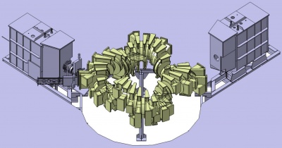
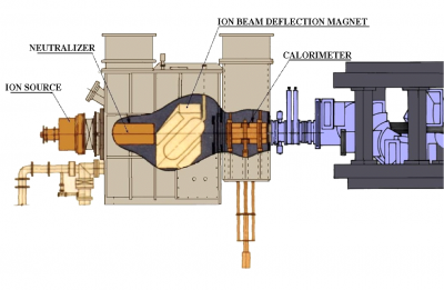
TJ-II disposes of two neutral beam injectors (NBI), each of which can produce ≤ 300 ms pulses of neutral hydrogen accelerated to 40 keV, to provide up to 1.2 MW of absorbed additional heating for central electron densities up to 1.6×10²⁰ m-3. [1] [2] [3]
NBI1 is located in sector D8. NBI2 is located in sector C1.
Power supply
The two high voltage power supplies feeding the acceleration grids of the injectors are of the transformer–rectifier type, taking their primary energy from a pulsed flywheel generator, and are coupled to the acceleration grids through a switching device. [4]
Control system
The NBI system has its own control system, based on VMEbus, with controller boards running the OS9 real-time operating system. [5] [6]
Vacuum system
In order to keep reionization losses at an acceptable level, the maximum allowed pressure during the beam pulse is 10−4 mbar, which requires an installed pumping speed of 350,000 l/s. Titanium getter pumps have been chosen as the primary vacuum system for these injectors. Base pressures in the range of 5 × 10⁻⁹ mbar are attainable with titanium pump operation. [7]
Calorimeter
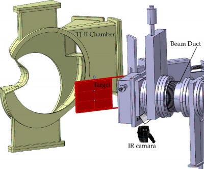
A carbon fiber composite (CFC) target calorimeter has been installed to study the power density distribution of the neutral beams in situ. The thermographic print of the beam can be recorded using an infrared camera, permitting a reliable analysis due to the highly anisotropic thermal conductivity of the target material. Direct conversion from temperature to power density is possible due to independent thermocouple measurements on two adiabatically mounted copper buttons. With the combined thermographic and calorimetric measurements it has been possible to determine the power density distribution of the beams. [8] [9]
References
- ↑ J. Guasp, M. Liniers, C. Fuentes, and G. Barrera, Thermal load calculations at TJ-II vacuum vessel under NBI, Fusion Tech., 35, pp. 32-41 (1999)
- ↑ C. Fuentes et al, Neutral beam injection optimization at TJ-II, Fusion Engineering and Design 74, Issues 1-4 (2005) 249-253
- ↑ M. Liniers, G. Wolfers,J.A. Sebastián, et al, Beamline duct monitoring of the TJ-II neutral beam injectors, Fusion Engineering and Design 88, Issues 6-8 (2013), 960–963
- ↑ J. Alonso et al, High voltage power supplies for the neutral beam injectors of the stellarator TJ-II, Fusion Engineering and Design 56-57 (2001) 693-697
- ↑ L. Martínez-Laso et al, TJ-II neutral beam injectors control and data acquisition system, Fusion Engineering and Design 56-57 (2001) 477-480
- ↑ R. Carrasco et al, The NBI control system for the TJ-II, Fusion Engineering and Design 81, Issues 15-17 (2006) 1813-1816
- ↑ M. Liniers et al, Vacuum system of the neutral beam injectors at the stellarator TJ-II, Vacuum 67, Issues 3-4 (2002) 379-384
- ↑ C. Fuentes et al, Thermographic calorimetry of the neutral beam injectors heating beams at TJ-II, Rev. Sci. Instrum. 77 (2006) 10E519
- ↑ C. Fuentes et al, Power transmission of the neutral beam heating beams at TJ-II, Fusion Engineering and Design 82, Issues 5-14 (2007) 926-932


