TJ-II:Electron Cyclotron Emission
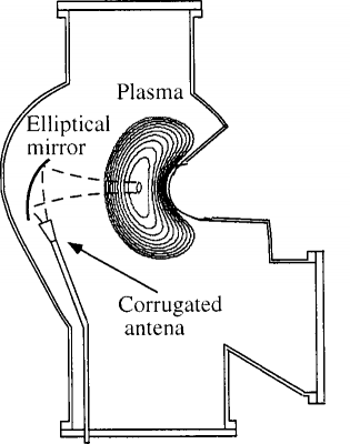
Electron temperature profiles are measured at TJ-II by means of a 16 channel heterodyne radiometer, covering the frequency range 50–60 GHz, corresponding to the second harmonic of electron cyclotron emission (ECE) in X-mode polarization at a magnetic field of 0.95 T on the plasma axis. The measurements are performed from the low field side (LFS) in the horizontal midplane (between sectors C4 and C5, φ = 315°), but most of the channels receive radiation from the high field side (HFS). In normal operation conditions, the frequency depends on a known way on the magnitude of the magnetic field B. Tuning properly the receiver system, each frequency corresponds to a different value of the major radius R (according to B(R)). The system is operated close to the strong ECR heating source (fECRH = 53.2 GHz). To protect the radiometer against stray radiation from the gyrotron, the radiometer band is split into two parts. The second harmonic emission above and below 53.2 GHz are measured separately by means of microwave couplers in the signal path.
Calibration
The system is calibrated absolutely by comparing room temperature with liquid nitrogen temperature. [1] [2] The optical system and the transmission line of the ECE diagnostic were designed to allow the calibration to be performed outside the vacuum vessel keeping the arrangement of the diagnostic. To calibrate, the transmission line is opened close to the diagnostic port (C5-bottom). Then the port flange, which holds the optical system and the wave-guide up to that point, is extracted from the torus and assembled with the same alignment outside the vacuum vessel. A check for the radiometer stability is performed periodically by using a stable noise source at the input of the radiometer. Such a noise source is also used to test the linearity of the system and to calibrate any possible change that may occur in the electronics of the diagnostic.
Data analysis
The emission can be simulated by the TRECE ray tracing code. [3]
The local radiation temperature is assumed to be a function only of the local electron temperature at the resonant layer; however, if the plasma is not Maxwellian or if the plasma is optically thin, the measured radiation temperature is no longer equal to the electron temperature. The effect of polarization rotation can be neglected once the correct polarization for the pure X mode on-axis is chosen. Even at high density (worst condition) the radiation coming from the plasma bulk experiences a rotation below 5°.[3] The spatial resolution is about 1 cm.[1]
The typical sampling rate is 100 kHz. The raw signals in the TJ-II database are called 'ECE1' ... 'ECE16', and the processed (calibrated) signals 'TECE1_' ... 'TECE16_' (units: keV).
References
- ↑ 1.0 1.1 E. de la Luna, J. Sánchez, V. Tribaldos, and T. Estrada, Multichannel electron cyclotron emission radiometry in TJ-II stellarator, Rev. Sci. Instrum. 72, 379 (2001)
- ↑ E. de la Luna et al, Electron cyclotron emission measurements on TJ-II stellarator plasmas, Fusion Engineering and Design 53, Issues 1-4 (2001) 147-151
- ↑ 3.0 3.1 V. Tribaldos and B. P. van Milligen, Electron cyclotron emission calculations for TJ-II stellarator, Nucl. Fusion 36, 283 (1996)
